When 4 mm² Is Too Thin and 6 mm² Is the Answer
On a long string run, 4 mm² is often the size that looks adequate on a short module tail and turns marginal over thirty metres. KUKA CABLE publishes the numbers that settle the argument: 4 mm² is 56 strands of 0.29 mm at 59 g/m, while 6 mm² is 84 strands at 78 g/m, and each carries a nominal outer diameter of 5.5 mm and 6.0 mm respectively.
Key takeaways
- Sizing is a comparison of published figures, not of labels: 4 mm² at 59 g/m against 6 mm² at 78 g/m on the manufacturer's table.
- Tinned copper conductors are class 5 flexible to IEC 60228, so both sizes are stranded, not solid.
- Bending radius is published as 4 × the outer diameter, which puts 4 mm² at roughly 22 mm and 6 mm² at roughly 24 mm on my own arithmetic.
- The operating window is the same for both: −40 °C to +90 °C ambient, with +250 °C permitted for 5 seconds under short circuit.
Why the label on the drum is not the answer
Cross-section decides three things at once: current-carrying capacity, voltage drop over the run, and mechanical strength at the clips. A short tail from a module to a rail can be served by 4 mm² without argument. The same size stretched down a row and back to a combiner box accumulates resistance over distance, and the loss appears as heat in the conductor rather than as watts at the inverter.
The manufacturer's own solar cable section describes 4 mm², 6 mm² and 10 mm² as the commonly used specifications, with single-core and twin-core versions available. That sentence is a starting point: the choice between the first two is yours to justify with numbers.
The published table, read properly
Four columns on the cross-section table do the work. The first is the nominal cross-section, the second the conductor construction as a strand count, the third the nominal overall diameter, and the fourth the nominal weight per metre. Read the last two together, because diameter drives the bend radius and the clip spacing while weight drives the drum handling and the freight calculation.
| Cross-section | Conductor construction | Nominal outer diameter | Nominal weight | Minimum bend radius at 4× diameter |
|---|---|---|---|---|
| 4 mm² | 56 × 0.29 mm | 5.5 mm | 59 g/m | about 22 mm |
| 6 mm² | 84 × 0.29 mm | 6.0 mm | 78 g/m | about 24 mm |
| 10 mm² | 142 × 0.29 mm | 7.5 mm | 130 g/m | about 30 mm |
| 16 mm² | 238 × 0.29 mm | 8.8 mm | 190 g/m | about 35 mm |
| 25 mm² | 375 × 0.29 mm | 11.0 mm | 292 g/m | about 44 mm |
| 35 mm² | 520 × 0.29 mm | 12.3 mm | 390 g/m | about 49 mm |
When 4 mm² still earns its place
Two situations keep 4 mm² in the schedule. The first is the short jumper between adjacent modules or between a module and the rail-level harness, where the run is measured in centimetres and the current is the current of a single string. The second is a project where the mechanical load on the clips matters more than the copper, because 59 g/m is a lighter cable to support across a long span of tray. The published row for a 4mm solar cable shows 56 strands of 0.29 mm inside a 5.5 mm overall diameter, which is the lightest build in the four-to-ten range.
The published insulation and sheath for the range are XLPO, electron-beam cross-linked and LSHF, on a tinned copper conductor that is class 5 flexible to IEC 60228. Those properties do not change between 4 mm² and 6 mm², so the choice is about the copper, not about the compound.
The case for stepping up to 6 mm²
Step up when the run gets long, when the array runs hot, or when the string current is at the top of the range you intend to use. The published resistance advantage of a larger conductor is not stated on the site as a volt-drop table, so the buyer has to do that part of the work and confirm it against the size the supplier recommends. What the site does state is the mechanical penalty: 6 mm² weighs 19 g/m more than 4 mm² on the published figures, and its diameter grows by 0.5 mm (my own subtraction of the two published values).
That is a small mechanical price. The strand count rises from 56 to 84, which keeps the conductor flexible for pulling through conduit even as the copper area grows. Both sizes share the published standard set: the 1500 V page names TUV 2PfG 1169/08.2007, EN 50618:2014 and IEC 62930, and the finish is XLPO insulation and sheath over tinned copper of class 5 to IEC 60228. A 4 mm² and a 6 mm² drum from the same range therefore arrive with the same safety story and a different copper weight.
Worked example: bend radius on the published diameters
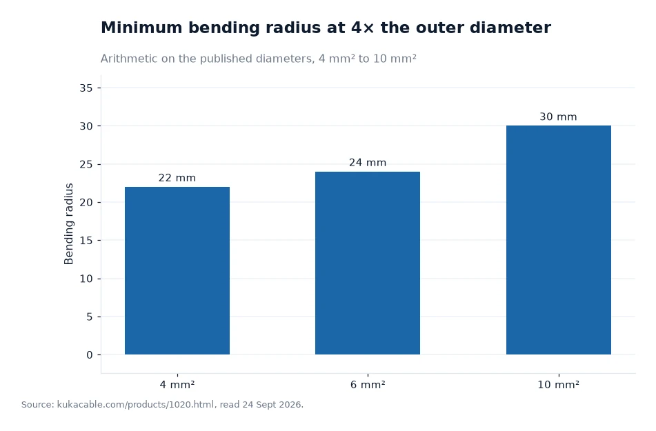
The rule published on the 1500 V solar cable page is a minimum bending radius of 4 × the outer diameter. Applying it to the cross-section table: 4 × 5.5 mm gives 22 mm for a 4 mm² cable, 4 × 6.0 mm gives 24 mm for 6 mm², and 4 × 7.5 mm gives 30 mm for 10 mm² (my own calculation, taking the nominal diameters as published). At 16 mm² the figure rises to about 35 mm from a published diameter of 8.8 mm.
The practical reading is that a 6 mm² cable needs a form of about 48 mm across its outer edge if it is bent through a half-turn, since the radius applies to the centreline and the diameter has to be added twice for a full U (my own reasoning, not a published figure). That is the number to check against the radius of your conduit bends and the depth of your junction boxes before the drums are ordered. Installers who work to the published figure rather than to feel avoid the crushed insulation that shows up later as an insulation-resistance fault.
Reading the bend-radius chart
The chart below plots the same arithmetic for three commonly quoted sizes. It comes from the manufacturer's published diameter data, and it is titled for what it is: the minimum bending radius at 4× the outer diameter. The bars sit at about 22 mm, 24 mm and 30 mm for 4 mm², 6 mm² and 10 mm². Nothing in it says which size to buy; it says how tightly each size may be pulled around a corner.
Frequently asked questions
Does a larger cross-section always lower the losses?
It lowers the resistance of the run, and resistance is what turns current into heat along the cable. The manufacturer's table gives the diameter and the weight for each size but not a volt-drop table, so the loss calculation stays with the system designer.
Can 6 mm² be used with the same connectors as 4 mm²?
The site lists MC4 and solar connectors, solar fuse connectors, solar diode connectors and PV cable assemblies as part of the same product family, and a solar connector page carries a CE and RoHS certificate download. Connector-to-cable compatibility has to be confirmed against the connector datasheet for the size in question.
What to write on the enquiry
State the run length, the string current, the ambient ceiling and the tightest bend on the route, then ask for the size the manufacturer recommends against those four numbers. Ask for the cross-section row for that size, so the strand count, diameter and weight can be checked against the drum label on delivery. The 1500 V solar cable data supplies the electrical and thermal limits, and the laboratory test list shows how the finished cable is checked before dispatch. KUKA CABLE offers a free sample on product pages, which is the simplest way to hold a 6 mm² offcut next to the conduit bend you are worried about.
Attribution for this cross-section comparison: the manufacturer's own website figures, with the bending radii tallied 24 Sept 2026[1].